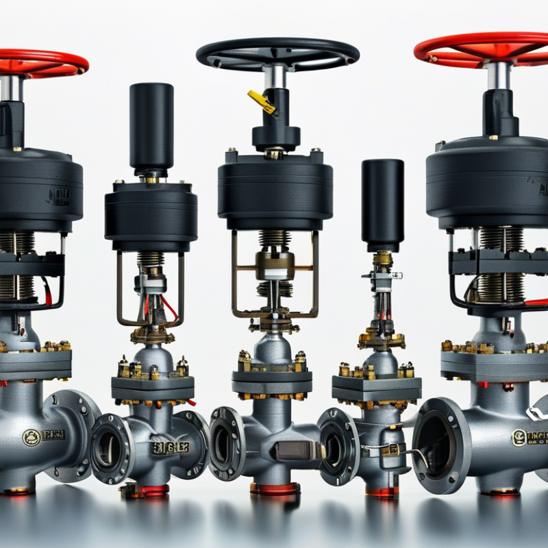
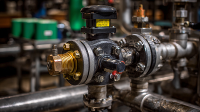
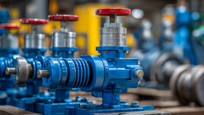
A motorized valve may look like a compact assembly of metal, wires, and fasteners. Inside, however, it combines fluid control with electrical movement. An electric actuator receives a signal, turns a stem or shaft, and changes the valve’s opening. That simple motion can regulate water, steam, air, fuel, or process chemicals with measured precision.
Dr. Béla G. Lipták, a respected process-control engineer, describes a control valve as “the final control element in a control loop.” His observation explains why a motorized valve matters. Sensors may detect temperature or pressure, and a controller may calculate the response. The valve still performs the physical correction.
This guide examines how the actuator, valve body, control signal, and feedback system work together. It also compares common designs, including ball, butterfly, globe, and damper valves. The discussion will connect technical theory with practical details, such as a humming actuator, a slowly rotating stem, or a valve that stops before reaching its expected position.
The process is not always perfect. A motorized valve can move correctly yet control poorly if sizing, wiring, or calibration is wrong. Moisture, excessive torque, corrosion, and incorrect fail positions can create less visible problems. Small errors matter.
Reliable selection therefore requires more than matching pipe size. Engineers consider pressure, temperature, flow direction, actuation speed, maintenance access, and safety requirements. Understanding these choices helps readers judge performance realistically, rather than trusting a product label alone.
A motorized valve controls liquid or gas flow through an electric actuator. A controller sends a signal, and the actuator moves the valve into an open, closed, or intermediate position. This arrangement supports remote control and repeatable operation in heating, cooling, water, and industrial systems.
The valve body contains the flow passage and internal shutoff element. Depending on the design, this element may be a ball, butterfly disc, globe plug, or gate. The stem transfers movement from the actuator to that element. Seals around the stem help prevent leakage, while internal seats create the closing surface. These parts experience pressure, friction, and temperature changes, so material selection matters.
The actuator contains a motor, gears, and electrical connections. Gears increase torque and control movement speed. Limit switches stop the motor at defined positions. Some actuators also include position feedback, allowing a controller to verify actual movement. A manual override can help during power loss or maintenance, but it should be used carefully. Some systems use spring return action for safer shutdowns. Others remain in their last position. That choice depends on the process risk.
In field inspections, a valve may receive a correct signal but fail mechanically. Dirt, incorrect wiring, worn seals, or insufficient torque can cause this problem. A motorized valve is not automatically reliable. Its performance depends on sizing, installation, calibration, and regular testing. There is no perfect arrangement for every pipeline.
A motorized valve controls liquid or gas flow with an electric actuator. Its operation begins when a controller sends an open, close, or modulating signal. The actuator receives power and turns a small motor. Gears increase the motor’s torque. This torque moves the valve stem, ball, disc, or plug. The valve then changes the passage opening. Simple movement, but not always simple control.
As the valve moves, internal limit switches or position sensors monitor its travel. When the selected position is reached, the actuator stops automatically. In a modulating system, the controller may send a partial-position signal. The valve then opens gradually, helping maintain pressure or temperature. A technician should check wiring, voltage, flow direction, and manual override access before testing. A loose connection can imitate a failed actuator. I have seen this mistake waste more time than the repair itself. The first test should be slow.
Tips: Match the actuator’s torque with the valve size and operating pressure. Keep the stem clean and aligned. Listen for grinding or repeated clicking. These sounds often indicate binding, incorrect limits, or worn gears. Never force the manual override while the motor is energized. A practical inspection log should record travel time, unusual noise, and final valve position. Even a small recording can reveal gradual failure.
A motorized valve combines a valve body, an electric actuator, and a control signal. The actuator turns a stem or shaft, changing the valve’s opening. A sensor or controller may then adjust flow, pressure, or temperature. Small movements matter. Poor sizing still causes noise, leakage, and unnecessary energy use.
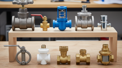
Motorized ball valves are common in water treatment, HVAC, and process piping. Their quarter-turn action provides quick shutoff and relatively low pressure loss. Butterfly valves also use quarter-turn actuation, but their lighter bodies suit larger pipe diameters. They are practical for cooling water and air systems. Globe valves offer better throttling control, although their curved flow path creates greater pressure loss.
Gate valves are mainly selected for isolation, not frequent adjustment. Diaphragm valves work well with corrosive, contaminated, or hygienic fluids because the diaphragm separates the mechanism from the medium. In field selection, this distinction is often missed. A valve that closes reliably may still control poorly.
The International Energy Agency estimates that electric motor systems consume about 46% of global electricity. This figure includes many systems beyond valves, but it highlights actuator efficiency.
The U.S. Department of Energy also estimates motor-driven equipment uses roughly 70% of industrial electricity.
Therefore, engineers should check torque, duty cycle, fail position, and control accuracy, not only purchase price. Even experienced teams sometimes choose a larger actuator “for safety.” That choice can increase cost, cycling stress, and power consumption.
What Is a Motorized Valve and How Does It Work?
A motorized valve uses an electric actuator to open, close, or regulate fluid flow. The actuator receives a signal from a controller, then turns the valve stem with measured force. This simple action supports accurate control of water, air, steam, and other approved fluids. Some systems use only open-or-closed positions. Others adjust flow continuously through proportional movement.
Motorized valves appear throughout modern buildings and industrial systems. In HVAC equipment, they regulate chilled water through cooling coils and protect comfortable room temperatures. Water treatment plants use them to direct water between tanks, filters, and dosing stages. Irrigation networks use timed valves to supply separate planting zones. Manufacturing lines may control process water, compressed air, or clean fluids. In a large building, one valve can quietly manage a rooftop heating loop while sensors monitor pressure and temperature nearby. Small failures matter. A stuck valve can waste energy, disturb production, or create uneven heating.
Tips: Match the actuator’s torque, voltage, and response time to the valve and system. Check the flow direction before installation. Test manual overrides during maintenance, not only during emergencies. Inspect wiring, seals, position feedback, and unusual vibration. A practical review should also consider what happens after power loss. The safest setting is not always the most obvious one. Designers sometimes overlook slow movement, especially when a valve appears correctly sized. Confirm actual operation under normal load, because a successful bench test may not reflect field conditions. Repair records should include valve position, observed noise, and response delay.
What Is a Motorized Valve and How Does It Work?
What Factors Should Guide Motorized Valve Selection?
A motorized valve combines a valve body with an electric actuator. The actuator turns a control signal into mechanical movement. This movement opens, closes, or adjusts fluid flow. In heating, cooling, irrigation, and process systems, that control can reduce manual intervention. However, selecting one requires more than matching pipe size.
Start with the medium. Water, steam, chemicals, and compressed air demand different materials and sealing methods. Check temperature, pressure, viscosity, and possible corrosion. A valve rated for clean water may fail quickly with abrasive fluid. Flow requirements matter too. An oversized valve can hunt between positions and waste energy. An undersized valve may restrict the system during peak demand.
Control compatibility deserves close attention. Confirm voltage, signal type, response speed, and fail-safe behavior. Some systems need a spring-return actuator during power loss. Others require a battery backup or manual override. Review the duty cycle, enclosure rating, installation space, and maintenance access. A compact actuator is not always the practical choice.
A common mistake is trusting catalog values without checking real operating conditions. Pressure drops, outdoor exposure, and frequent cycling can change performance. Ask for tested torque data, certification documents, and clear service instructions. Selection is rarely perfect on the first review. Recheck assumptions with operators and installers before approval.
| Selection Dimension | Common Options or Data | How a Motorized Valve Works or What to Check | Selection Guidance | Typical Use |
|---|---|---|---|---|
| Basic Definition | Valve body + electric actuator + control interface | An electric motor drives a gearbox, stem, or rotary coupling to open, close, or position the valve. Limit switches, position sensors, or torque protection stop or monitor travel. | Confirm whether the application requires simple isolation or continuous modulation. | Water, HVAC, process lines, utilities |
| Valve Movement | Quarter-turn or multi-turn | Quarter-turn valves rotate approximately 90° and commonly use a ball, butterfly, or plug design. Multi-turn actuators move a rising or non-rising stem and are commonly used with gate or globe valves. | Match actuator output motion and travel with the valve stem or shaft. | Isolation, throttling, flow control |
| Valve Type | Ball, butterfly, globe, gate, or plug | Ball and butterfly valves are generally quarter-turn designs. Globe valves are commonly selected for more precise throttling. Gate valves are mainly intended for on/off isolation rather than routine throttling. | Select according to shutoff, pressure drop, control accuracy, and available installation space. | Pipeline and equipment isolation or regulation |
| Control Function | On/off, floating, or modulating | On/off control commands fully open or fully closed travel. Floating control uses open/close pulses. Modulating control uses a proportional signal, commonly 0–10 V or 4–20 mA, to position the valve. | Use a modulating actuator only when intermediate flow positions are required and the valve is suitable for throttling. | Zone control, temperature control, process regulation |
| Flow Medium | Water, air, steam, gas, oil, chemicals, or slurry | Medium properties affect body material, seal material, corrosion resistance, cavitation risk, erosion, and actuator sizing. | Check viscosity, abrasiveness, chemical compatibility, solids content, and cleanliness before selecting materials. | HVAC, water treatment, industrial processing |
| Pressure and Temperature | Operating pressure, differential pressure, and temperature | Valve ratings are defined by the valve design, pressure class, materials, and temperature. Differential pressure can substantially increase the torque or thrust required for operation. | Use the maximum normal and abnormal operating conditions, not only the average values, for sizing. | Steam, hot water, compressed air, process service |
| Size and Connection | Nominal pipe size and connection standard | Common connections include threaded, flanged, wafer, lug, and welded ends. The valve bore and flow coefficient influence capacity and pressure loss. | Match nominal size, face-to-face dimensions, flange drilling, pressure rating, and installation orientation. | Retrofit and new piping systems |
| Flow Capacity | Cv or Kv, flow rate, and allowable pressure drop | Cv and Kv describe the valve's flow capacity under specified test conditions. An oversized valve may operate near its seat and provide unstable control. | Size from required flow and pressure drop; avoid selecting solely from pipe size. | Hydronic systems and process control |
| Actuator Output | Torque for rotary valves; thrust for linear valves | The actuator must overcome seating, unseating, packing, bearing, and fluid-related forces throughout the complete travel. | Use the valve manufacturer's required torque or thrust, then include an appropriate engineering margin without causing excessive oversizing. | All motorized valve applications |
| Power Supply | Common supplies: 24 V AC/DC, 110–120 V AC, or 220–240 V AC | The actuator motor, control electronics, and fail-safe mechanism must be compatible with the available voltage, frequency, and current capacity. | Verify start-up current, wiring method, electrical classification, and compatibility with the building or plant control system. | Building automation and industrial panels |
| Fail-Safe Requirement | Fail-open, fail-closed, fail-in-place, or manual override | A spring-return actuator can drive the valve to a predetermined position after power loss. Non-spring-return actuators generally remain in position or require a backup power source, depending on design. | Choose the safe position based on fire protection, freeze protection, pressure relief, process safety, and personnel safety. | Heating, cooling, fuel, and emergency systems |
| Operating Speed | Travel time from seconds to several minutes | Fast movement can create water hammer, pressure surges, or process instability. Slower movement may be preferred for large pipelines and sensitive systems. | Set the required travel time according to pipe volume, fluid velocity, control-loop response, and surge limits. | Large water lines and precision control loops |
| Duty Cycle | Occasional operation or frequent modulation | Actuators have operating-time, starts-per-hour, and thermal limits. Frequent positioning generates more heat and mechanical wear than occasional isolation. | Check rated duty cycle, expected cycles per hour, modulation frequency, and motor thermal protection. | On/off service, HVAC modulation, process control |
| Position Feedback | Auxiliary switches, potentiometer, 0–10 V, or 4–20 mA feedback | Feedback confirms valve position to a controller or monitoring system and can support alarms for incomplete travel or abnormal operation. | Specify feedback accuracy, signal type, isolation, and whether end-position indication is sufficient. | Remote monitoring and closed-loop control |
| Environmental Protection | Indoor, outdoor, wet, dusty, corrosive, or hazardous area | Enclosure protection, corrosion-resistant materials, cable entry, ambient temperature, and hazardous-area certification affect actuator reliability. | Select the required ingress protection and hazardous-area certification based on the actual installation environment. | Outdoor plants, washdown areas, chemical facilities |
| Manual Operation | Handwheel, declutch mechanism, or emergency override | A manual override permits operation during commissioning, maintenance, or loss of electrical power, subject to the actuator design. | Provide a safe and accessible override where continuity of service or maintenance access is important. | Remote stations and critical utilities |
| Control-System Integration | Relay control, analog signal, fieldbus, or networked control | The actuator may receive commands from a switch, programmable controller, building automation system, or industrial control network. | Confirm input/output signal compatibility, communication protocol, fail-state behavior, and alarm requirements. | Automated plants and smart building systems |
| Maintenance Factors | Seal replacement, lubrication, inspection, and calibration | Wear can occur at seals, seats, stems, gears, bearings, and electrical contacts. Modulating service may accelerate seat and actuator wear. | Review spare-part availability, access for service, cycle life, inspection intervals, and documentation requirements. | Continuous-duty and difficult-access installations |
| Installation Orientation | Horizontal, vertical, or manufacturer-specified position | Some valve and actuator assemblies have restrictions related to stem orientation, drainage, condensation, cable entry, or actuator weight. | Follow the installation instructions and maintain enough clearance for removal, wiring, and manual operation. | Compact mechanical rooms and skid systems |
| Selection Priority | Safety, performance, compatibility, lifecycle cost | A suitable motorized valve must meet process requirements while remaining reliable under the actual electrical, mechanical, and environmental conditions. | Prioritize correct sizing, material compatibility, fail-safe behavior, control integration, and maintainability over the lowest purchase price. | General engineering selection |
| Note: Exact pressure, temperature, flow, torque, thrust, duty-cycle, enclosure, and service-life ratings vary by valve and actuator design. Final selection should be verified against the manufacturer's technical documentation and the system's maximum operating conditions. | ||||

Accreditations
ISO 9001 Quality Management
HSE Management Compliant
Products and services comply with relevant Australian (AS) and international (ISO, etc.) Standards.
"*" indicates required fields