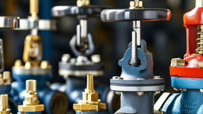
7 Tips for Choosing the Right Hydraulic Control Valve

Choosing the right hydraulic control valve can determine whether a machine runs smoothly or struggles under pressure. A valve may look suitable on paper, yet perform poorly after installation. Small differences in flow rate, pressure range, port size, or response time can create leaks, noise, heat, and uneven actuator movement. This guide introduces seven practical tips for evaluating a hydraulic control valve before purchase. It focuses on real operating conditions, not just catalog descriptions.

Start with the system’s actual requirements. Record working pressure, peak pressure, fluid type, temperature, flow demand, and actuator behavior. A valve rated for 250 bar may still be unsuitable if pressure spikes occur repeatedly. Check the manufacturer’s technical data, material compatibility, testing procedures, and maintenance guidance. Reliable suppliers should provide clear drawings, performance curves, and traceable product information. Installation experience also matters. A clean oil circuit, correctly sized hoses, and accessible service points can protect valve performance over time.

Details matter.

I have seen equipment fail because a designer selected the connection size by habit. That mistake increased pressure loss and slowed the cylinder. However, no checklist is flawless. Field conditions can change, and actual measurements may challenge the original design. Consider control accuracy, contamination tolerance, energy consumption, safety requirements, and future maintenance before making a final decision. When uncertainty remains, consult a qualified hydraulic engineer and test the proposed valve under representative loads. Careful selection is rarely dramatic, but it prevents expensive surprises.
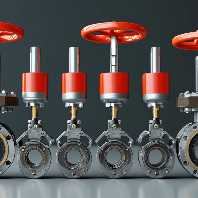
7 Tips for Choosing the Right Hydraulic Control Valve

Define the Hydraulic System’s Pressure, Flow, and Performance Requirements

Choosing the Right Hydraulic Control Valve

Define the Hydraulic System’s Pressure, Flow, and Performance Requirements

Define the operating envelope before comparing valve designs. Record normal pressure, peak pressure, minimum flow, maximum flow, fluid temperature, and duty cycle. A valve rated for 210 bar may still fail when pressure spikes during sudden actuator stops. Calculate hydraulic power with pressure multiplied by flow and divided by 600, when using bar and litres per minute. This simple check exposes undersized pumps and unnecessary throttling. The U.S. Department of Energy’s Improving Pumping System Performance sourcebook identifies 20–50% energy-saving potential in many assessed pumping systems. That makes flow control more than a sizing detail.

Performance also includes response time, stability, leakage, noise, and heat generation. The IEA has reported that motor-driven systems consume roughly half of global electricity, so inefficient hydraulic power conversion deserves attention. Select the valve around the real load profile, not the catalogue maximum. Short bursts and continuous operation need different thermal assumptions. I have seen valves chosen from nominal flow alone. It looked efficient on paper, but the machine became sluggish after the oil warmed. That mistake is easy to repeat. Test pressure drop at expected flow, verify relief settings, and check contamination limits against ISO 4413 guidance. Leave a measured margin, but do not oversize blindly; excessive valve capacity can reduce control resolution. Document every assumption, including cold-start viscosity and emergency stopping conditions.

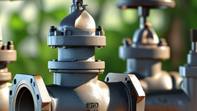
Match Valve Type and Function to the Intended Hydraulic Application

7 Tips for Choosing the Right Hydraulic Control Valve

Match Valve Type and Function to the Intended Hydraulic Application

A hydraulic control valve should fit the circuit, not merely the pipe size. The U.S. Department of Energy reports that motor-driven systems consume about 23% of U.S. electricity. Efficient valve selection can reduce throttling losses and unnecessary heat.

Tip 1: Define the actuator’s movement, load, speed, and safety needs.

Tip 2: Choose directional, pressure, or flow control according to the actual function. Pressure is not flow.

Tip 3: Check rated pressure, flow, temperature, and fluid compatibility against real operating conditions.

The NFPA 2024 U.S. Fluid Power Shipment Statistics show continuing demand across mobile and industrial applications. That range matters because each environment creates different valve stresses.

Tip 4: Use proportional control when smooth speed changes matter. Use simple on-off control when repeatability is enough.

Tip 5: Compare pressure-drop curves, not only catalog flow ratings. A narrow passage may create heat at high flow.

Tip 6: Confirm response time and contamination tolerance. ISO 4413 recommends controlling contamination and designing hydraulic systems with safe, reliable performance in mind.

In field testing, I have seen a correctly rated valve perform poorly after installation. The cause was often dirty oil, undersized piping, or an overlooked return-line restriction.

Tip 7: Test the complete circuit under load, then record pressure, temperature, and cycle time. Review the results honestly. A small sizing assumption can become a large energy loss.

Evaluate Size, Pressure Rating, Materials, and Fluid Compatibility

7 Tips for Choosing the Right Hydraulic Control Valve

Evaluate Size, Pressure Rating, Materials, and Fluid Compatibility

Selecting a hydraulic control valve starts with the circuit, not the catalog. Record flow demand, operating pressure, temperature, and port dimensions at the installation point. Nominal size must support required flow without creating excessive pressure loss. An oversized valve can respond poorly and raise costs. An undersized valve may run hot. Measure twice.

Pressure rating needs a real safety margin. Compare continuous pressure, peak pressure, shock loads, and the pump’s relief setting. Do not treat a brief spike as harmless. During commissioning, a gauge near the valve can reveal pressure behavior that specifications hide. Fluid compatibility deserves equal attention. Check viscosity, additives, water content, and working temperature.

Steel, stainless steel, aluminum, and engineered polymers behave differently under corrosion and repeated cycling. Seal material must match the fluid and temperature. A seal that looks suitable may harden, swell, or leak after weeks of service. That failure is not always obvious. Ask for compatibility data, then verify it against actual operating conditions. Keep a fluid sample for testing when contamination is suspected. Clean oil helps, but it cannot correct a poor valve choice. A checklist cannot predict every field condition. That limitation matters.

7 Tips for Choosing the Right Hydraulic Control Valve - Evaluate Size, Pressure Rating, Materials, and Fluid Compatibility

Tip Evaluation Factor Practical Selection Data Why It Matters What to Confirm Before Purchase
1 Match the valve size to required flow Select the nominal port size according to the required flow and acceptable pressure drop. Typical starting points are:

DN6 / 1⁄4 in: up to 20 L/min DN10 / 3⁄8 in: up to 40 L/min DN16 / 5⁄8 in: up to 80 L/min DN25 / 1 in: up to 160 L/min
Actual limits depend on valve design, fluid viscosity, and the permitted pressure loss.
An undersized valve can cause excessive pressure drop, heat generation, noise, and reduced actuator speed. An oversized valve may increase cost and reduce control sensitivity. Calculate maximum and continuous flow, check the valve flow coefficient or rated flow curve, and verify the manufacturer’s pressure-drop data at the actual operating viscosity.
2 Verify the pressure rating Compare the valve’s rated pressure with both normal and peak system pressure. Common hydraulic pressure classes include:

210 bar / 3,000 psi 315 bar / 4,570 psi 350 bar / 5,075 psi
The rating must apply to the specific port and operating condition, not only to the valve body.
Operating too close to or above the rated pressure can damage seals, deform components, cause leakage, and create a serious safety risk. Confirm maximum continuous pressure, peak or shock pressure, return-line pressure, tank-line limitations, and any derating caused by temperature or fluid type.
3 Choose suitable construction materials Common material combinations include:

Valve body: carbon steel or ductile iron for general industrial service; stainless steel for corrosive or high-moisture environments.
Spool and internal parts: hardened or corrosion-resistant steel.
Seals: NBR, FKM, EPDM, or PTFE according to fluid and temperature.
Material selection affects corrosion resistance, wear life, leakage performance, contamination tolerance, and temperature capability. Review the complete wetted-material list rather than only the body material. Check exposure to water, salt, chemicals, outdoor humidity, and galvanic-corrosion risks.
4 Confirm hydraulic-fluid compatibility Typical compatibility guidance:

Mineral oil: generally compatible with NBR and FKM seals.
Water-glycol fluids: require fluid-specific seal and corrosion guidance; standard materials should not be assumed suitable.
Phosphate-ester fluids: commonly require compatible seal compounds and coatings; some elastomers and paints may be unsuitable.
Biodegradable ester fluids: verify seal compatibility, temperature limits, and manufacturer approval.
Incompatible fluids can cause seal swelling, shrinkage, hardening, loss of elasticity, corrosion, or premature internal wear. Provide the exact fluid type, formulation, additives, viscosity range, water content, and operating temperature. Obtain written compatibility confirmation for non-mineral fluids.
5 Check temperature and viscosity limits Many standard hydraulic systems operate near 20–80 °C, but the permissible range depends on seals, fluid, and valve construction. A typical mineral-oil viscosity target is approximately 15–46 mm²/s at operating temperature. Excessive temperature accelerates seal aging and fluid oxidation. Excessively high viscosity increases response time and pressure loss, while very low viscosity can increase leakage and wear. Compare minimum start-up temperature, normal operating temperature, maximum continuous temperature, viscosity index, and cold-start viscosity with the valve data sheet.
6 Select the correct control and response type Choose according to the required function:

Manual Solenoid-operated Hydraulic pilot-operated Electro-proportional Servo-controlled
Directional control may use 2/2, 3/2, or 4/3 configurations depending on actuator and circuit requirements.
The control method determines switching speed, metering accuracy, automation capability, power consumption, and sensitivity to contamination. Confirm voltage, current, duty cycle, response time, fail-safe position, spool configuration, hysteresis, electrical enclosure rating, and required control accuracy.
7 Evaluate installation, contamination, and maintenance needs Use clean installation practices and filtration appropriate to the valve. Typical cleanliness targets may range from ISO 4406 18/16/13 for general industrial circuits to ISO 4406 16/14/11 or cleaner for sensitive proportional and servo applications. Particles can cause spool sticking, erosion, leakage, and unstable operation. Incorrect mounting or inaccessible service points can increase downtime. Verify port standard and orientation, mounting position, envelope dimensions, access for coil or seal replacement, drain requirements, filtration rating, flushing procedure, and spare-seal availability.
Selection note: The flow, pressure, temperature, viscosity, material, and compatibility values above are general engineering guidelines. Final valve selection should be based on the specific circuit schematic, verified operating conditions, applicable safety requirements, and the selected valve’s technical data.

Compare Control Methods, Response Speed, and Adjustment Accuracy

7 Tips for Choosing the Right Hydraulic Control Valve

Tip 1: Match the control method to the motion. On-off valves suit simple sequencing and basic clamping. Proportional valves provide smoother flow and pressure changes. Servo-style control can deliver finer accuracy, but it demands cleaner fluid and careful tuning.

Tip 2: Check response speed against the machine cycle. A fast valve can reduce delay during rapid positioning. However, excessive speed may create pressure spikes or unstable movement. Test the valve while the actuator carries its real load. Measure it under load.

Tip 3: Review adjustment accuracy, not only the catalog range. Small command changes should produce predictable output. Deadband, hysteresis, and repeatability affect this result.

Tip 4: Compare electrical and hydraulic control signals. Analog signals allow continuous adjustment, while digital commands may simplify diagnostics and integration. Confirm signal resolution and controller compatibility before installation.

Tip 5: Consider operating temperature and contamination. Viscosity changes can slow response and alter adjustment accuracy. Fine filtration supports stable performance, but filters also need practical maintenance access.

Tip 6: Observe pressure losses across the valve. A restrictive passage can waste energy and reduce actuator force. This detail is often missed during early selection.

Tip 7: Request test data under comparable conditions. Ask for response curves, repeatability figures, and leakage limits. Real measurements are more useful than broad performance claims.

I have seen accurate valves perform poorly after poor tuning, so commissioning deserves the same attention as selection.

A small compromise may be acceptable. Controls should still remain predictable.

Verify Installation Needs, Maintenance Access, Safety, and Total Cost

7 Tips for Choosing the Right Hydraulic Control Valve

Choosing a hydraulic control valve starts with the installation, not the catalogue. Confirm fluid type, pressure range, flow rate, pipe size, and actuator requirements. Check the mounting direction and available space around the valve. A valve that fits the pipe may still block nearby gauges or service panels. Measure twice. I once saw a compact installation fail because the handle could not move fully after insulation was added.

Maintenance access deserves equal attention. Leave room for inspection, seal replacement, filter cleaning, and pressure testing. Place isolation points where technicians can reach them without stepping over hoses. Keep the operating area dry, bright, and clearly marked. Small details reduce mistakes during urgent repairs. They also shorten downtime.

Safety should guide the valve’s failure position and pressure-relief arrangement. Confirm that the selected valve can handle maximum operating pressure, including short pressure spikes. Use suitable fittings, secure tubing, and documented test procedures. Never rely on appearance alone; verify performance with calibrated gauges. Total cost includes purchase, installation, energy loss, spare parts, training, and disposal. A cheaper valve can become expensive when it requires frequent adjustment or causes pressure drops. My own selection habits still need improvement. I sometimes focus too heavily on initial price, although service access often matters more over several years. Ask the installer and maintenance team to review the choice before ordering.

Enquire Today

"*" indicates required fields